


0. Test transferring packages
File sending test1(2022.3.1):
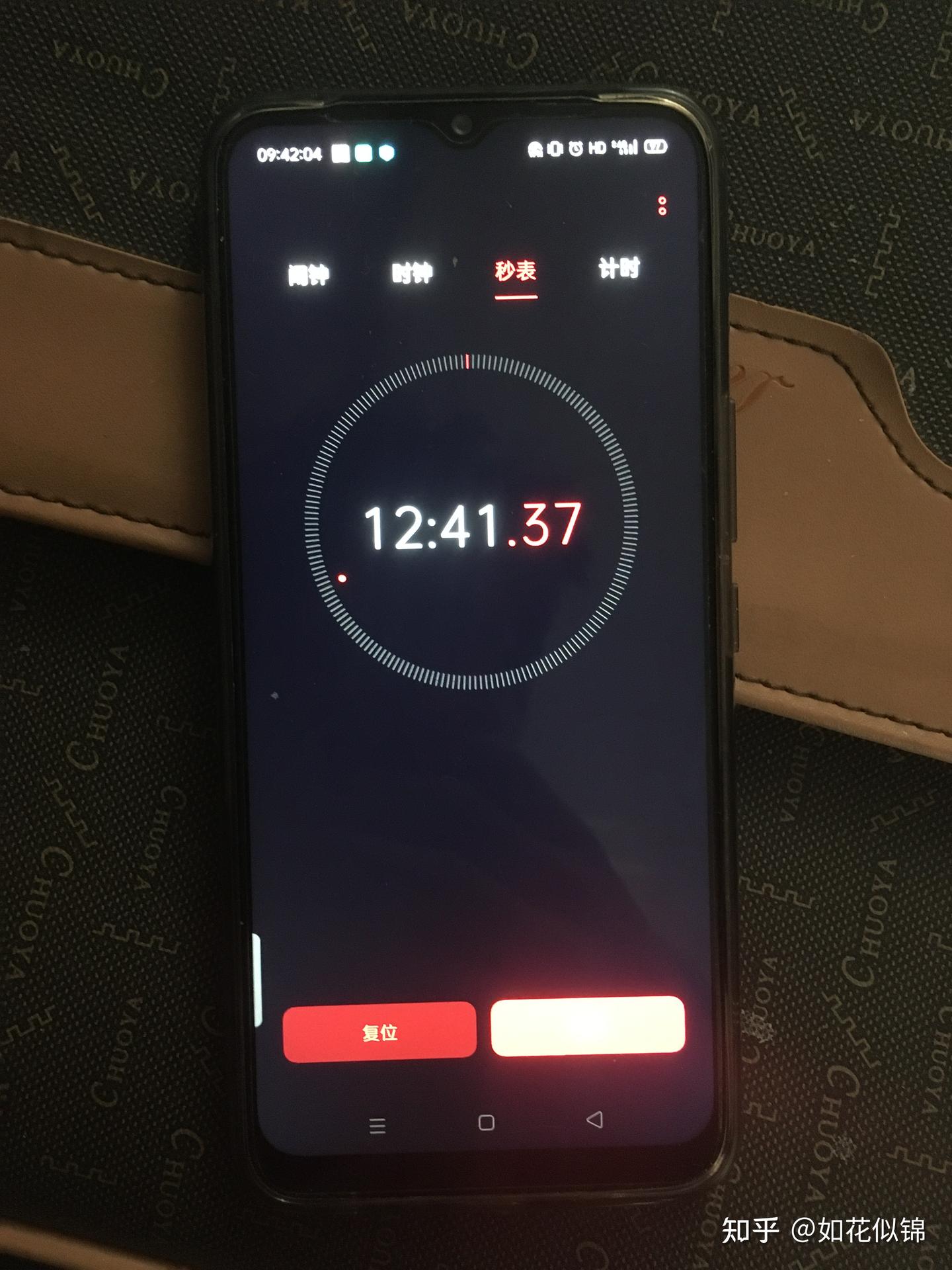
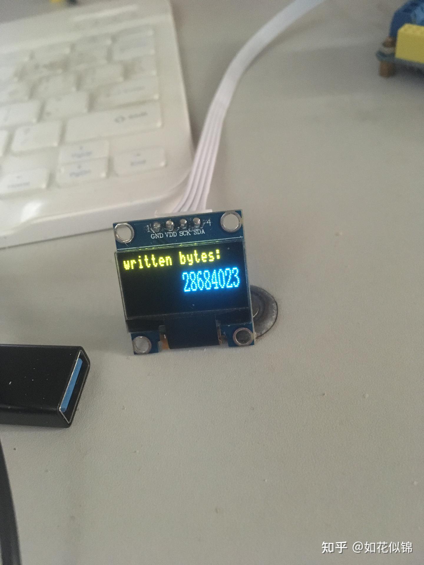
The transmission speed has been increased to 40–46 kb/s. I tested a file of 28,684,023 bytes (approximately 28 MB). The transmission took 12 minutes and 41 seconds, which corresponds to an effective throughput of 37 KB/s.
File sending test2:
— プログラミング君 (@lovejp_1) December 3, 2021
1. What is that?
I am currently working on my undergraduate thesis, which focuses on laser-based file transmission. The project itself is not extremely difficult, but completing everything on my own has been very time-consuming. It took me more than half a month to design the overall system architecture and to complete the 3D model of the laser receiving module. The file-processing system for the laser transmission took another week or so to finish. (The main reason for the long development time is that, as an undergraduate, I was learning many of the required concepts and tools while building the project.)
The testing machine section of my graduation thesis has been successfully completed, and I have already received both my degree certificate and graduation certificate. Within a week, I will upload the source code, 3D models, and circuit diagrams to my personal website and share them on Zhihu as well. Those with strong hands-on skills are welcome to try building the system themselves. (Updates coming soon.)
Encoding scheme: ON–OFF keying.
Maximum error-free data rate: 40 kb/s – 46 kb/s at a baud rate of 460,800. [Data rate = baud rate × log₂(N) (N = 2 for binary) / 10 (one start bit, one stop bit, eight data bits).]
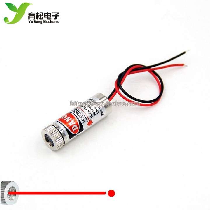
Laser module used: 650 nm, 5 mW visible red laser.
Processing chip: STM32F103ZE, equipped with 512 KB of flash memory.
Communication protocol: Asynchronous serial (UART).
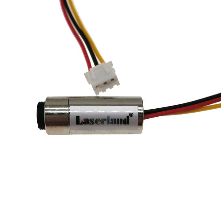
I also tested a more expensive 980 nm laser module, but the improvement in data rate compared with the inexpensive laser was limited. However, the cheap laser has significant beam divergence. In my tests this was not noticeable because the transmission was only across my desk, from the left side of the computer to the right.
2. 受信機回路
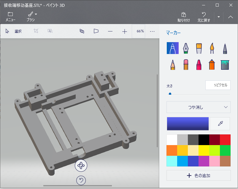
3. 調整可能受信機:
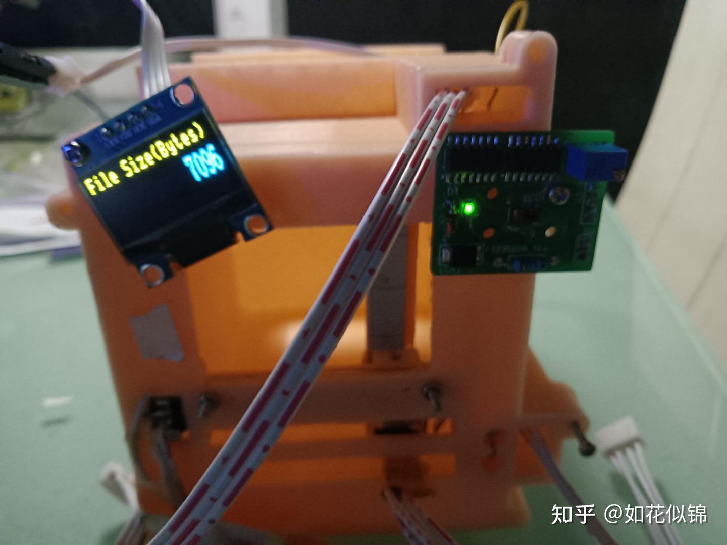
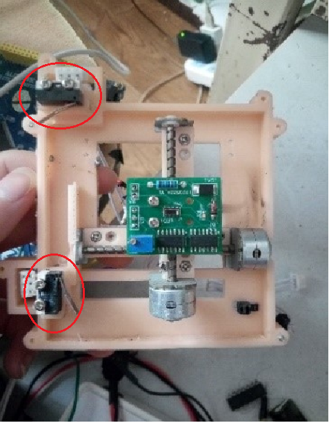
As shown in the figure, the laser-receiving board is actually mounted on two micro stepper motors for laser positioning. On the back side, there is another PCB that integrates more than one hundred photoresistors (each 1.6 × 1.2 mm), also used for laser alignment. When one of the photoresistors detects the laser spot, it returns the detected position, and the stepper motors then move to that position for laser reception.
Since I am currently performing file error-rate testing, the system is not fully assembled yet, so it temporarily looks like the setup shown in the figure. The two micro stepper motors are also connected to limit switches, which are used to locate the home (zero) position.
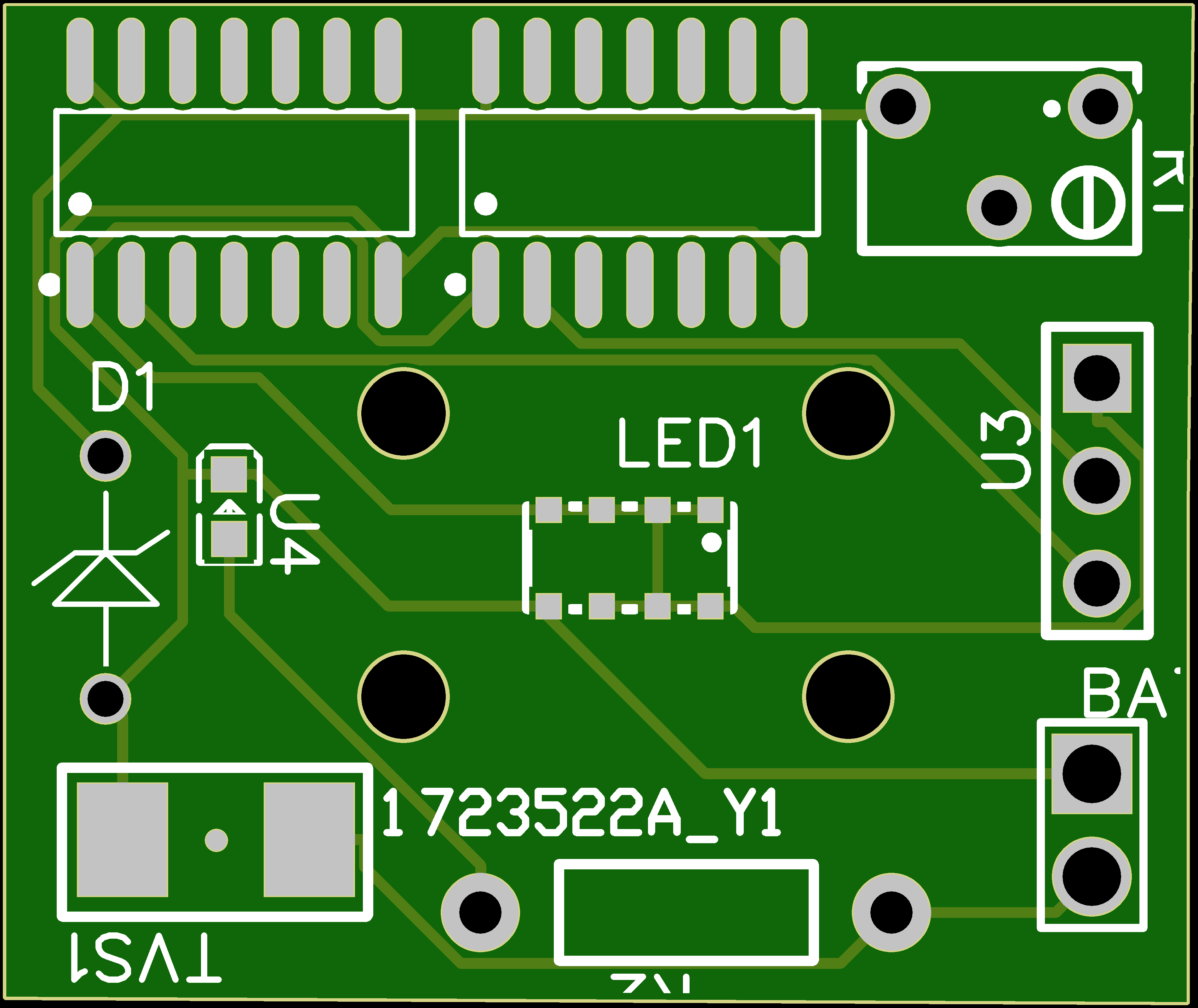
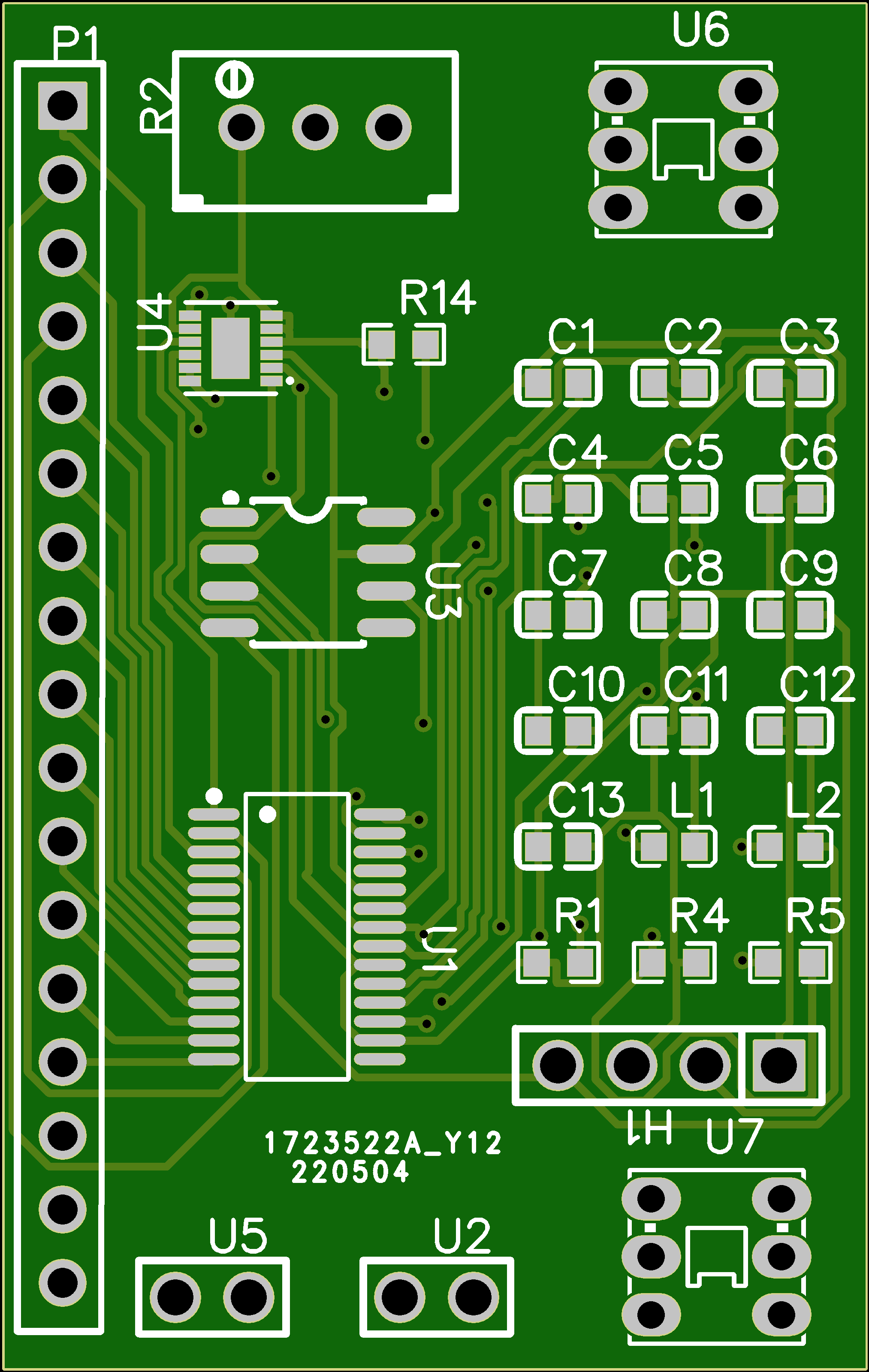
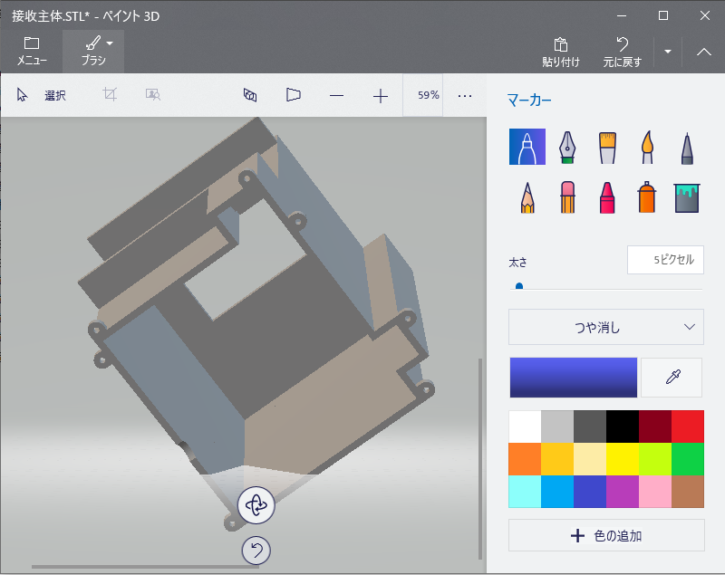
4. 基板とモデル
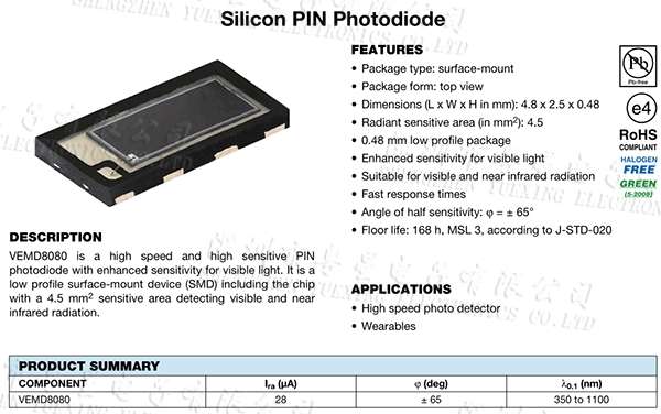
5. PIN diode とレーザー
6. Earlier album
変圧器で音楽を伝送#変圧器 pic.twitter.com/oUYjzTatV1
— プログラミング君 (@lovejp_1) December 30, 2021
レーザー vs LED 音楽を転送効率。聞いてみよう。レーザーのはよりも長い距離を転送できて、だから、ledのはもっとはっきりとしている#光転送 pic.twitter.com/mHaHwuyCC2
— プログラミング君 (@lovejp_1) December 8, 2021
レーザーで音楽を転送するイアフォンそのものだ!今僕はレーザーでデータを転送する課題を集中している。 pic.twitter.com/KnE5CBP2YA
— プログラミング君 (@lovejp_1) November 26, 2021
テスト第一回。レーザー通信でdata転送するためには不可視レーザーの位置づけることは不可欠で、大変難しいなのでこんな装置は良い#不可視レーザー定位 pic.twitter.com/IYPIQfZnKd
— プログラミング君 (@lovejp_1) January 4, 2022
Comment Section